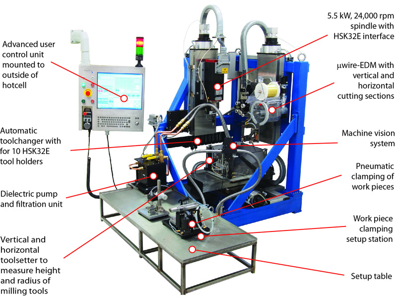
4-Axis Hybrid Machining Center (VHMC01) - Radiation hardened
VHMC01 is a hybrid machining center that combines high-speed milling
with micro-wire electrical discharge machining (mWEDM) in a single
machine. Designed and built to machine highly radioactive materials, the
machine features an extremely small footprint (900 x 900 mm = 35.4 x
35.4 in) and low machine height (1400 mm = 55 in) to allow it to be
placed inside a hotcell to shield the operator from gamma radiation.
 Download Brochure
Overall Specs
- Small overall size (900 x 900 x 1400 mm)
- 300 x 300 mm work volume
- Pneumatic work clamping
- 19” color touchscreen with dual USB ports
- Keyboard + trackball + CNC pendant
- 4-axis control
- Mill and WEDM work piece offsets
- G-Code compatible (32,000 lines max)
- Integrated machine vision system
- Designed for gamma radiation (5x10⁷ rad)
- Made in the USA
|
Mill Specs
- 24,000 rpm inline direct drive HSK32E spindle
- 5.5 kW (7.5 hp) vector drive
- 10 HSK32E automatic tool changer
- Integrated vertical and horizontal tool setter
- Touch probe for work piece setup
WEDM Specs
- Versatile mEDM discharge generator
- 0.05 - 0.2 mm EDM wire w/o changing hardware
- Vertical + horizontal cutting sections
- Synthetic dielectric oil
|
 |
| VHMC01 is located inside a
hotcell and remotely operated with master-slave manipulators |
Highspeed Milling
 |
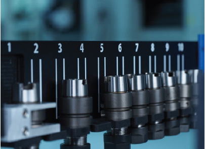 |
| Toolrack for 10 HSK32E tool
holders. Slot #1 is reserved for touch probe |
 |
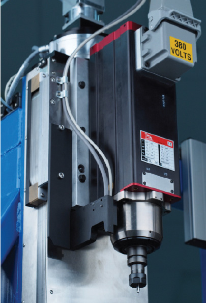
| Highspeed
spindle, 5.5 kW, 24,000 rpm |
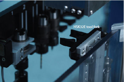
Pneumatic
tool lift with HSK32E tool fork is mounted to work tank
|
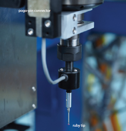
The work piece location is identified with a touchprobe that is
mounted in a HSK32E toolholder and located in the tool rack in slot #1.
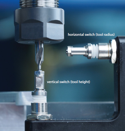
The tool height and tool radius of all milling tools can be set with the
vertical and horizontal toolsetter that consists of microswitches with a
repeatability of less then 0.0005 mm (0.00002 in).
 |
 |
|
The touch probe utilizes a pogo-pin connector that
establishes electrical connection as the tool holder is inserted
into the spindle |
The tool setter features a vertical and horizontal
microswitch with 0.0005 mm repeatability that measures the tool
height and tool radius |
Micro-Wire Electrical Discharge Machining
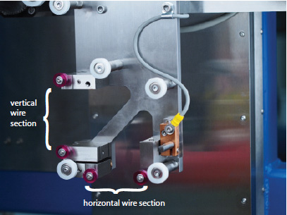
The micro-wire EDM head is mounted to the rear vertical axis (W-axis)
and features a unique wire guide setup that creates both a vertical and
horizontal wire section. The dual sections greatly increase
manufacturing flexibility and reduce the need for changes in work piece
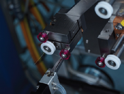
setup. Each wire guide is mounted to a flexure-based micro stage with
micro adjuster to achieve perfect wire alignment of both sections.
Automatic wire threading is performed with a wire gripper that threads
the wire from the supply spool around each of the wire guides and
pulleys to the takeup spool. Wire spools are held magnetically to
facilitate operating the machine with master-slave manipulators. The
dielectric fluid is a synthetic EDM oil that requires no maintenance
besides filtering.
 |
 |
|
A single wire is exposed at two separate locations,
thereby creating a vertical and horizontal wire section for
increased manufacturing flexibility |
Micro-flexure stages allow the vertical and horizontal
wire sections to be aligned with the principal machine axes. The
wire gripper performs wire threading through pre-programmed
coordinated XYW motion. |
 |
 |
|
The tensioning required for delicate micro wires is
achieved through a friction-only brake system based on the
Capston effect around ceramic wheels |
The wire tension servo system is based on the
displacement of linear springs that is measured with extreme
accuracy by a LVDT |
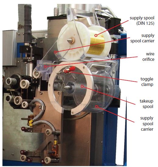 |
The wire system features a standard DIN 125 wire spool that is
loaded outside the hotcell into a custom spool carrier. The
carrier has strategically located magnets that create a highly
repeatable position of the carrier and its wire orifice during
loading with a master-slave manipulator. The accurate position
of the wire orifice is of critical importance to the reliability
of the automatic wire threading process as it defines the pickup
point of the wire with the pneumatic gripper.
The spent wire is wound onto a takeup spool that is partly
surrounded by an insulating cover. In the case of wire breakage,
any excess wire is first pulled onto the takeup spool where the
cover prevents loose ends from touching the conductive parts of
the machine. The new wire, after it is threaded around all
required pulleys and guides, is fixed to the spool with a toggle
clamp that is closed using the manipulator. Similar to the
supply spool carrier, the takeup spool carrier is located inside
a carrier that is magnetically registered onto the machine.
|
|
The wire system uses custom carriers that allow a
manipulator to load a standard EDM wire spool into the machine.
The spent wire is pulled onto a takeup spool and disposed off
together with its carrier. |
The wire threading process, while largely automated, requires manual
intervention throughout the process. The process itself is guided
through messages that are displayed in the control screen. First, the
axes are moved into safe positions that prevent collision of the
machine. Next, the user is asked to raise the wire gripper to its
vertical position using the manipulator. Upon confirmation, the wire
gripper is moved to the wire pickup point and the wire is grabbed with
the pneumatic gripper. Next, the user is asked to cut the excess wire to
the left of the wire gripper. This is achieved by using the manipulator
to squeeze a pair of wire cutters that are part of the supply spool
carrier. The excess wire is to be removed from the machine with the
manipulator. Upon confirmation, the machine starts the actual threading
process by guiding the wire around each of the required pulleys and wire
guides. The threading process ends with the wire placed at the clamping
point of the takeup spool. Next, the user is asked to close the toggle
clamp and to lower the threading arm to its retracted position. Upon
confirmation, the wire system winds up the wire for 3-4 turns to finish
off the threading process.
Work Piece Clamping
The work piece clamping system on the VHMC01 is a pneumatically powered
Universal Clamp (UC) with a short-stroke (3 mm) front and and a
medium-stroke (30 mm) side clamp. Work piece specific jaws are mounted
to the stationary and moving parts of the UC to hold a variety of work
pieces. The Universal Clamp is registered inside the work tank with
locator pins and held securely using pneumatic swing clamps. For work
piece setup, the Universal Clamp is removed from the work tank with
manipulators and placed into the external setup station, whose pneumatic
slip-on connections power and control the Universal Clamp in the same
way as the work tank does. During transfer between external setup
station and work tank, the Universal Clamp is without pneumatic
pressure. During this time, an internal spring system maintains
sufficient clamping force to keep the work pieces secure.
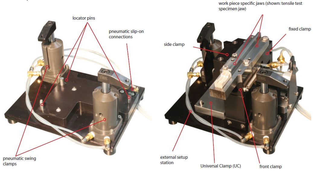 |
| The external setup
station contains the same pneumatic connections and swing clamps
as the work tank. This allows the Universal Clamp (UC) to be
operated both inside the machine as well on the setup table. |
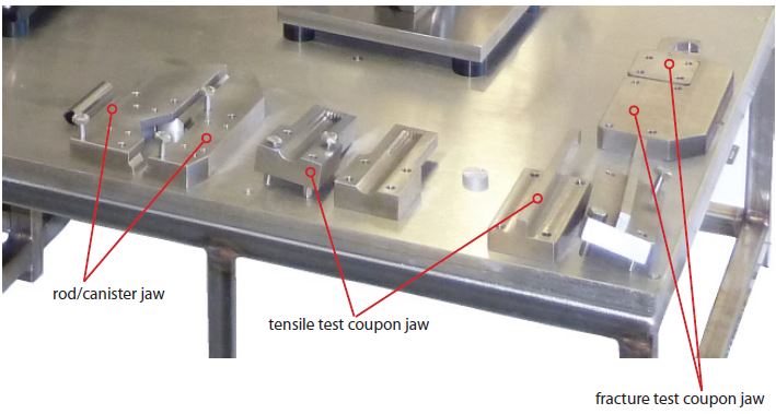 |
The work piece specific jaws mount to the
Universal Clamp (UC) with captive screws and are registered with
diamond pins. The tensile test specimen and fracture coupon test
specimen jaws utilize the short-stroke front clamp while the
rod/canister jaws utilize the side clamp.
The clamps are designed such that the complex geometries of both
the tensile test as well as the fracture test coupons can be
machined in a single setup without any changes to the work piece
setup. |
| The machine comes with 2
sets of work piece specific jaws that mount to the Universal
Clamp with captive screws and diamond pins. Shown are the
rod/canister jaw, the tensile test coupon jaw, and the fracture
test coupon jaw. |
Dielectric System
The dielectric system consists of an electric pump, a filtration unit
with user replacable cartridges, manual diverter valves, flexible hoses,
and a storage tank. The filtration unit features a large hex nut that
pulls the filter body, which is mounted on a spring-loaded vertical
slider with bottom pivot against the filter port (fixed). After the hex
nut is loosened, the filter is dropped down by pushing the filter handle
with the manipulator and then flipping it to the left. This creates
access for the manipulator to the filter cartridge. After the cartridge
is replaced, the filter housing is again pushed down and then flipped to
the right. Releasing the filter handle causes the spring-loaded slider
to push the filter housing upwards against the filter port. Tightening
the hex nut then seals the unit.
The manual diverter valves allows the system to be operated in four
distinct modes: Filling and draining of the work tank as well as
circulation of fluid inside the work and the storage tank. The
circulation modes are particular useful for cleaning the dielectric
fluid either during or after machining since the fluid is repeatedly
passing through the filter. This cleaning process ensures that the
majority of radioactive material particles are trapped in the filter
cartridge which can readily be disposed after machining, thereby leaving
the machining center largely free of contaminated materials. The pump is
protected by a pressure switch, which shuts off the pump when the
pressure inside the filter reaches 35 psi.
The dielectric system except for the filter housing is mounted on a
single plate and connected electrically to the rest of the machine using
slip-on connections. Therefore, after loosening the 3 captive screws,
the entire unit can be lifted off the storage tank and taken out of the
hotcell for servicing or replacing.
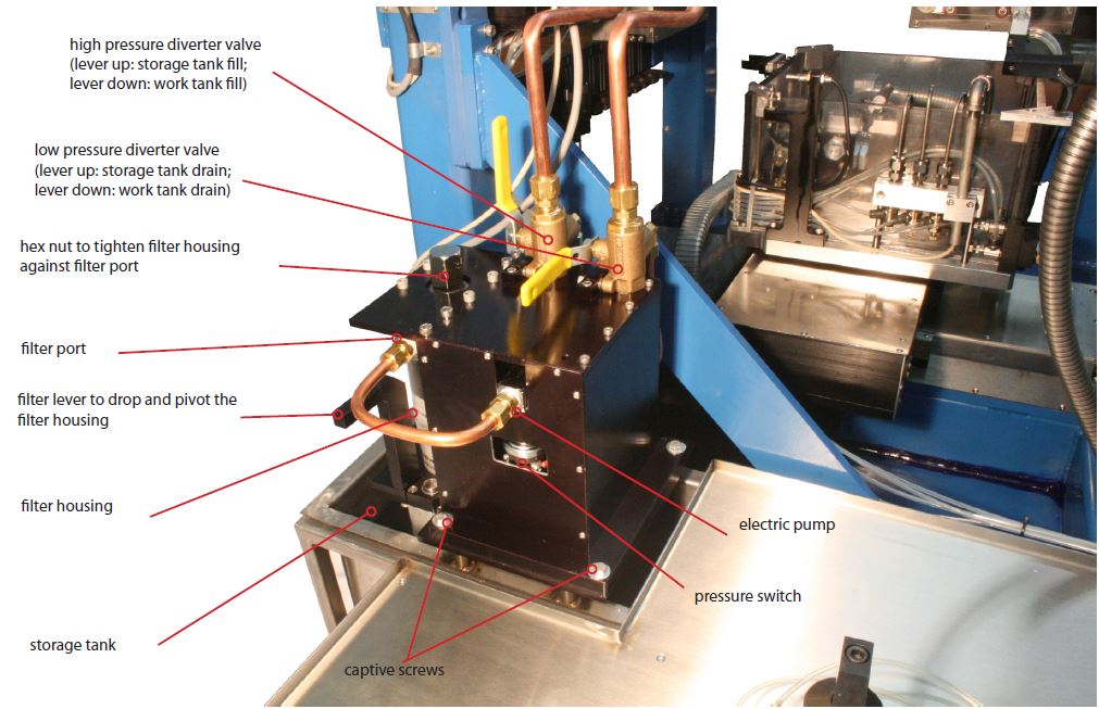 |
| The dielectric system is bolted
onto the storage tank using captive screws. The electric slip-on
connections allow the entire module to be lifted off the tank
once the captive screws are loosened. This allows the unit to be
removed from the machine and taken out of the hotcell for
servicing or replacing. |
Controls
The user interface (MicroPEC 5) was specifically created for
touchscreens. On the left 1/3 of the screen, critical information about
machine status such as axis position, EDM status, process overrides,
etc. is provided. The upper portion of the right 2/3 of the screen are
tabbed according to distinct operation modes. Shown in the picture is
the “Tool Setup” tab, which provides controls and information that are
relevant for setting up the milling tools (T1 - T10), operate the
10-tool changer, and perform the EDM wire threading process. Also
provided is a permanent touchscreen keyboard for manual data entry. This
is particularly useful for the creating G-Code on the machine and
setting or changing of tool and work piece offsets.
Other tabs provided relate to the setup of the work piece (Work Piece
Setup), allow manual data to be entered (MDI), the running of machining
programs (Machining), the sampling of coordinate measurement points of
work pieces using the touch probe, the EDM wire, or the external
measurement station (CMM), and a live video stream that is captured by
the on-machine vision system (Video).
MicroPEC 5 performs machining by executing G-Code that includes the full
set of EDM parameters. The controls allows up to 3 work piece offsets
(G54 - G56) to be set up with the EDM wire (for WEDM operations) and
another 3 offsets (G57 - G59) to be set up with the touch probe (for
milling operations). A unique feature of MicroPEC is that setting up
work piece offsets is performed by automatically taking into
consideration the probe size (EDM wire or touch probe) as well as the
approach direction, thereby eliminating the need for manual
modifications. Milling and EDM operations do not require separate
G-Codes because a specific code (M-Code) can be set to define the
machine mode (milling vs. EDM).
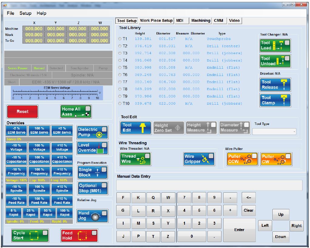 |
| MicroPEC is
optimized for a touchscreen interface and provides separate
tabbed screens for uncluttered presentation of individual
machine functions |
| |
|
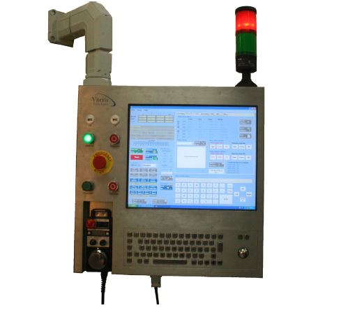
The control module is mounted to the
outside of the hotcell with a swing arm that allows the user to
orient the module freely. It features a 19” touchscreen and a
full-size keyboard with integrated trackball. Critical machine
functions such as cycle start/stop, power on/off, and emergency
stop are handled by hardware buttons.
Not shown in the picture is a removable CNC pendant with
magnetic backing and 3 m (10 ft) of coiled cabeling. The
pendendant has a jog wheel to move any of the 4-axis in
switch-selectable increments. Furthermore, pressing one of the
two dedicated jog buttons allows for continuous jogging at a
switch-selectable jog speed. For additional safety, the pendant
is also equipped with an emergency stop button. |
 |
| |
The control module is housed in a stainless steel
enclosure that is mounted on a swing arm. It features a 19”
touchscreen, full keyboard, trackball, and dedicated buttons for
critical machine functions. A removable CNC pendant is housed in
the lower left recess. |
|
|
|
|
|
Machine Vision System
Micromachining inside a hotcell poses a challenge for the operator.
The machine is located at considerable distance and separated by thick
leaded glass, which leads to greatly reduced visibility. Delicate
operations such as setting up the work piece offsets or manually
navigating a tool inside the work space without causing collisions can
be a real challenge.
As an aid for the operator, VHMC01 is equipped with a machine vision
system based on an industrial USB camera that is mounted on a movable
support. Using the manipulator, the camera can be repositioned to
capture any view of interest. The live video stream from the camera is
displayed in the control screen on the “Video” tab. The camera is
relatively inexpensive and is expected to need replacing after prolonged
exposure to gamma radiation.
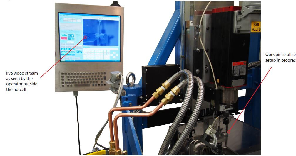 |
| The on-machine camera provides a
clear video stream of the work piece setup using the touch probe |
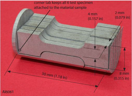
Work Pieces
 |
 |
| Tensile test
specimen from Al6061 machined in a single setup using the
vertical and horizontal WEDM of the VHMC01. Six samples can be
machined together from a rod section of 32 mm (1.26 in) length
and 16 mm (0.63 in) diameter. The samples remain attached to the
work piece by small tabs in the lower left corner and can be
snapped off later using the manipulator. |
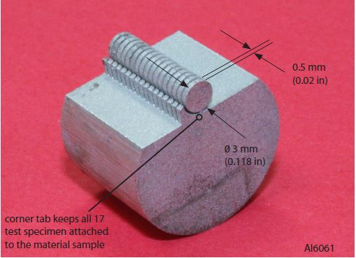
TEM (transmission
electron microscopy) samples are machined as disks with 3 mm
(0.118 in) diameter and 0.5 mm (0.02 in) thickness. 17 disks are
machined together from a 12 mm (0.47 in) section in a single
setup using the vertical and horizontal WEDM of the VHMC01. The
disks remain attached to the work piece by small tabs at the
bottom and can be snapped off later using the manipulator. |
 |
 |
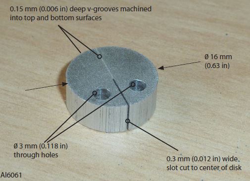
| Fracture toughness test specimen
cut on VHMC01 in a single setup. First, the milling spindle
center drilled and then drilled two diameter 3 mm (0.118 in)
holes. Next, the horizontal WEDM machined two v-grooves with
0.15 mm (0.006 in) depth into the center of the top and bottom
surfaces. Finally, the vertical WEDM machined a 0.3 mm (0.012
in) wide slot from the outside to the center of the disk. The
machining was programmed in a single G-Code file, combining the
milling, the horizontal and the vertical WEDM instructions. |
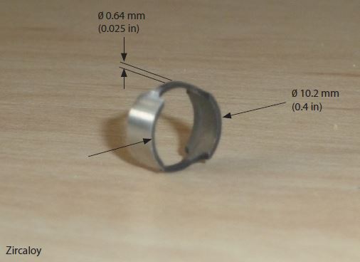
Ring compression
test specimen machined from tubular Zircaloy in a single setup
using the vertical WEDM of VHMC01 |
Overall Specs
- Size (w x d x h): 900 x 900 x 1400 mm (35.4 x 35.4 x 55
in)
- Weight: 500 kg (1,100 lbs)
- Workvolume: 300 x 300 x 145 mm (11.8 x 11.8 x 5.7 in)
- Dielectric tank: 40 l (10.6 gal)
- Dielectric filter size (user selectable): 0.001 - 0.01
mm (0.00004 - 0.0004 in)
- Axis resolution: 0.0005 mm (0.00002 in)
- Axis travel: 375 mm (14.76 in)
- Overall accuracy: 0.003 mm / 100 mm (0.00012 in / 4 in)
- Work piece fixturing: removable, pneumatic clamp
- Supply voltage: 415 VAC (3-phase) @ 20 A
- Air pressure: 7 bar (100 psi)\
|
Mill Specs
- Spindle power: 5.5 kW
- Spindle speed: 20 - 24,000 rpm
- Tool interface: HSK32E
- Automatic toolchanger: 10 toolholders
- Mill tool setup: vertical and horizontal tool setter
Control Specs
- User interface: 19” touchscreen + keyboard + trackball +
CNC pendant
- G-Code compatible (32,000 lines max)
- Work piece setup: touch probe in HSK tool holder + EDM
wire
Machine Vision Specs
- Camera: PixeLINK PL-E421CU (USB 2.0)
- Pixel pitch: 3.2 x 3.2 µm (0.00012 x 0.00012 in)
- Detector size: 1/3”
- Update rate: 28 fps
- Resolution: 1280 x 1024 pixels
|
WEDM Specs
- Discharge voltage: 10 - 135 V
- Discharge capacitance: 10 - 1300 nF
- Wire tension: 0.1 - 30 N (0.022 - 6.6 lbs)
- Wire speed: 5 - 200 mm/s (0.2 - 8.0 in/s)
- Wire size: 0.05 - 0.2 mm (0.002 - 0.008 in)
- Wire guide opening (fixed): 75 mm (3.0 in)
- Wire guide type: universal v-groove
- Wire orientation: vertical + horizontal
- Dielectric fluid: synthetic EDM oil
CMM Accuracy Specs
- Touch probe: ± 0.010 mm (0.0004 in)
- EDM wire: ± 0.008 mm (0.0003 in)
- External CMM station: ± 0.001 mm (0.00004 in)
|
|